Heat Exchangers
When you want to know how things really work, study them when they’re coming apart.
—William Gibson
What is a heat exchanger?
A heat exchanger is a device or system used to transfer thermal energy between materials, typically two fluids or a solid and a fluid.
Types of heat exchangers
Below are some of the common types of heat exchangers.
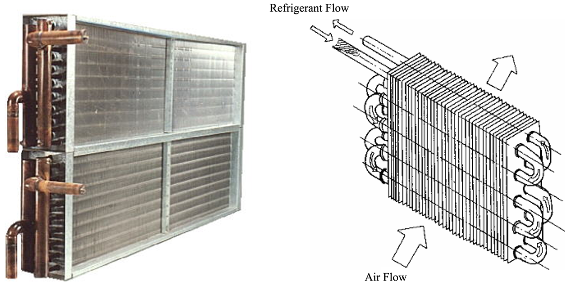
Fin and tube
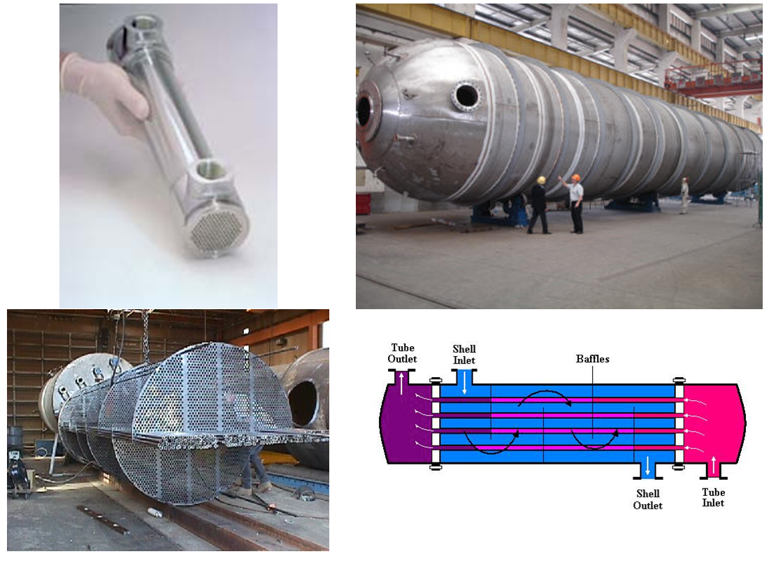
Shell and tube
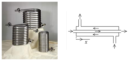
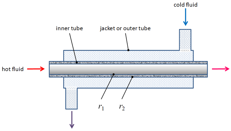
Tube in tube
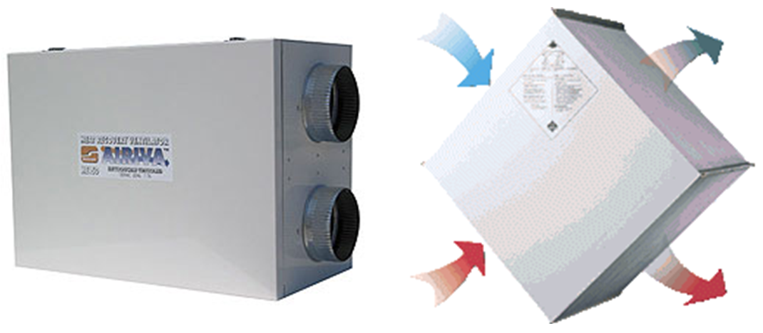
Air to air
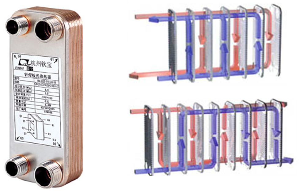
Brazed plate
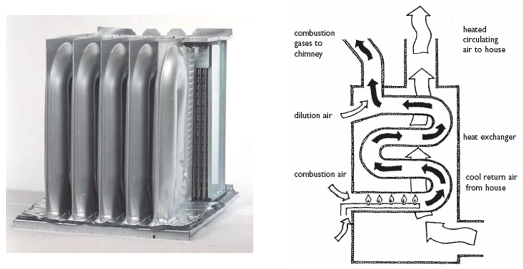
Combustion
Heat exchangers in nature
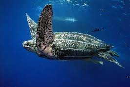
Anatomical Evidence for a Counter-current Heat Exchanger in the Leatherback Turtle (Greer, Lazell, and Wright, Nature 244, 181, 1973)
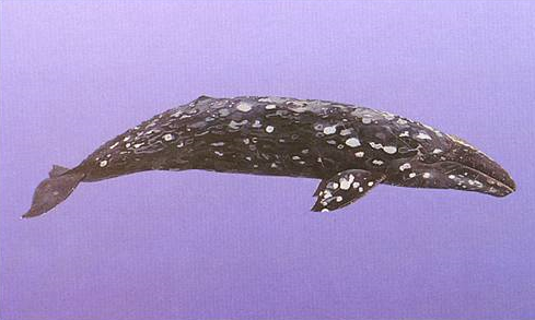
Thermoregulation in the Mouths of Feeding Gray Whales (Heyning and Mead, Science, 278, 7, 1997)

Bill of toco toucan acts as a heat exchanger to regulate body temperature by adjusting blood flow
Heat exchanger analyses
We’ve seen resistances a number of times already. The heat transfer resistances concept is particularly useful in heat exchanger analyses.
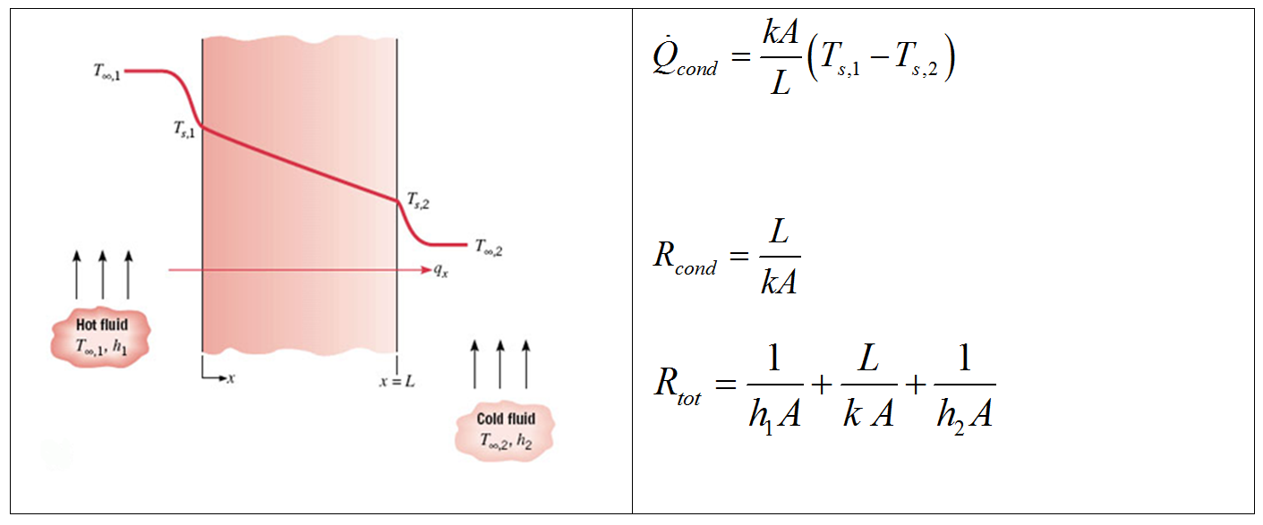
The overall heat transfer coefficient
The form of Newton’s law of cooling is very convenient. It would be nice if we could apply this same formalism for a series of resistances.
This is the idea behind the form of the heat exchanger design equation:
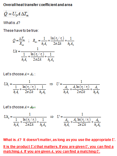
For now, let’s focus on \(U_{0} \, A\) and delay our discussion of the temperature driving force, \(\Delta T_{m}\), until a bit later.
A very useful concept that goes along with total resistances is the overall heat transfer coefficient.
Term |
Meaning |
Typical units |
|---|---|---|
\(U_{0}\) |
overall heat-transfer coefficient |
\(\si{W/m^{2}.K}\) |
\(A\) |
area over which transfer occurs |
\(\si{m^{2}}\) |
\(R_{\text{tot}}\) |
total heat transfer resistance |
\(\si{K/W}\) |
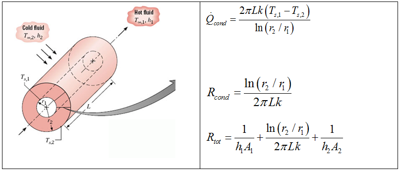
For a Cartesian (e.g., plane wall) case, the areas associated with each heat transfer process are the same. For the cylindrical (e.g., pipe) case, this is not true.
See this document
for information related to the appropriate area to use in the heat exchanger
design equation.
In an actual heat exchanger, we need to account for a number of resistances on the cold and hot sides.
Exercise: Heat exchanger - heat transfer resistances
Consider this heat exchanger:
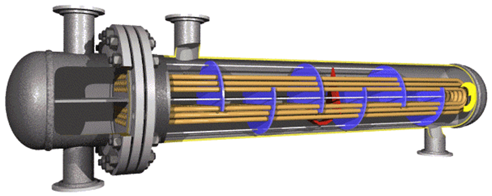
What type is it?
What are the the various heat transfer resistances?
Another heat exchanger resistance
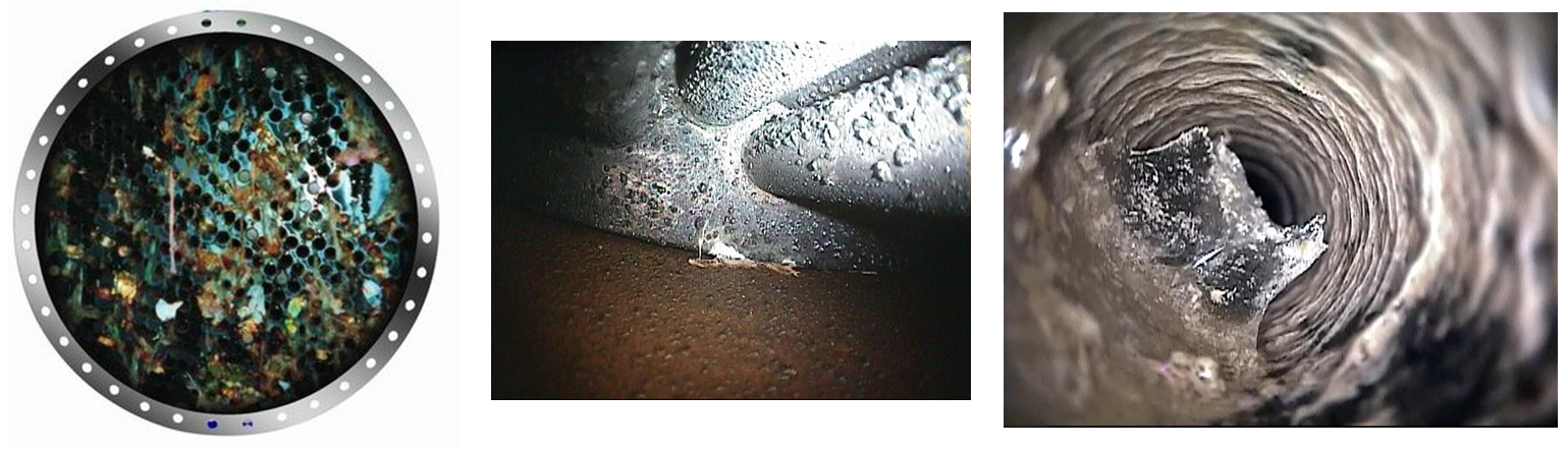
What do these represent? Fouling
Including fouling, the overall resistance is the sum of the individual resistances:
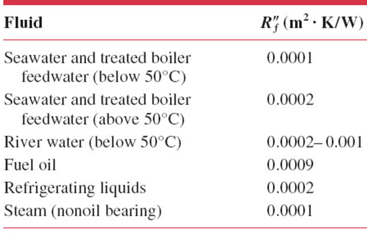
The new terms here are the fouling resistances, \(\frac{R^{''}_{f}}{A}\), which have units of \(\si{m^{2}.K/W}\).
What magnitude are fouling factors? Are they significant?
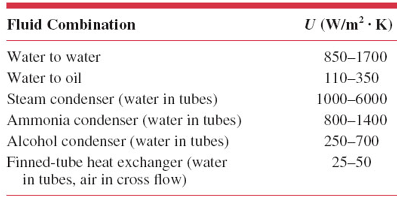
What are the magnitudes of overall heat transfer coefficients for heat exchangers?
Team Exercise: The Effect of Fouling on Heat Exchanger Performance
Due to poor maintenance practices, a tube-in-tube heat exchanger has significant fouling on the inner and outer surfaces of the inner heat transfer tube.
You have the following specifications:
Inner tube effective length, \(L=\SI{1}{m}\)
Inner tube wall thermal conductivity, \(k = \SI{15.1}{W/m.K}\)
inner tube: inner surface |
inner tube: outer surface |
|---|---|
\(r_{1} = \SI{0.75}{cm}\) |
\(r_{2} = \SI{0.95}{cm}\) |
\(h_{1} = \SI{800}{W/m^{2}.K}\) |
\(h_{2} = \SI{1200}{W/m^{2}.K}\) |
\(R^{''}_{f,1} = \SI{0.0004}{m^{2}.K/W}\) |
\(R^{''}_{f,2} = \SI{0.0001}{m^{2}.K/W}\) |
Recall that
Tasks:
compute the fraction of resistance from each source
calculate the overall heat transfer coefficient based on the inner surface area
identify the most promising ways to improve the heat exchanger performance.
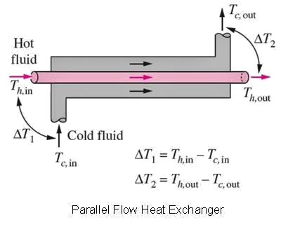
Temperature Profiles through the heat exchanger
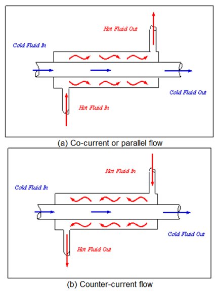
Although there are a number of flow configurations, we will focus on two: counterflow and parallel (or co-current) flow.
Exercise: Temperature profiles in a heat exchanger
Assume that the inner tube contains a hot fluid and the outer jacket contains a cold fluid.
Sketch out the temperature profiles for flow down the length of a parallel (co-current) flow and counterflow heat exchanger.
Analysis methods
Imagine this simple heat exchanger:
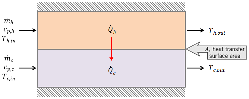
What do we know about the heat transfer rates?
How can they be computed?
The heat transfer rate can be computed from either the hot side or cold side. Recalling that we are losing thermal energy from the hot stream and gaining the energy in the cold stream, we can write
How else can we estimate a heat transfer rate?
We can compute it based on an appropriate overall heat transfer coefficient and temperature driving force using our heat exchanger design equation:
So, assuming that there is no heat loss,
Temperature driving force
Question:
Noting that the temperature changes down the length of the heat exchanger, what is the appropriate \(\Delta T_{m}\)?
That is, what temperature difference between the hot and cold sides will be representative of the ‘true’ driving force?
Answer:
The log-mean temperature difference (\(\Delta T_{\text{log mean}}\), \(\Delta T_{lm}\)):
So, in summary
Heat exchanger analysis/design equations
Comparing heat exchanger designs
A useful measure when looking at the heat transfer alone (not other factors, like pressure drop) is the ratio of heat transfer rates:
Exercise: Heat exchanger comparison
Assume that you need to cool \(\SI{1000}{kg/hr}\) of a product stream using cooling water. Both streams have the same specific heat capacity (\(c_{p} = \SI{4.191}{kJ/kg.K}\)). The stream temperatures are as follows:
\(T_{\text{water,in}} = \SI{7}{\degree C}\) |
\(T_{\text{water,out}} = \SI{27}{\degree C}\) |
\(T_{\text{product,in}} = \SI{95}{\degree C}\) |
\(T_{\text{product,out}} = \SI{49}{\degree C}\) |
1. Given the inlet and outlet temperatures below, how much cooling water will be needed (kg/hr)?
2. If the overall heat transfer coefficient is measured to be \(\SI{50}{W/m^{2}.K}\), what would be the required heat transfer area (in units of \(\si{m^2}\)) for a parallel (co-current) flow heat exchanger?
3. Repeat part 2 for a counterflow heat exchanger.
4. Is there a difference in areas between the heat exchangers in parts 2 and 3? Why or why not?
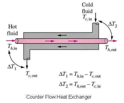
Exercise: Log mean temperature difference
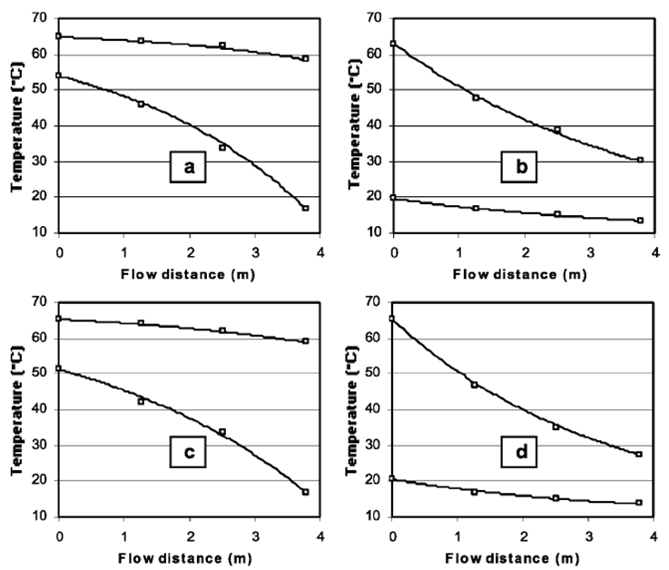
Find the log-mean temperature difference (LMTD, \(\Delta T_{lm}\)) for panels (a) and (b) below, assuming a counterflow heat exchanger.
Estimate a flow distance at which the temperature difference between the streams matches the LMTD.