|
|
HYDROLOGICAL AND SEDIMENT PROCESSES | ||||||||||||||||||||||||||||||||||||||||||||||||||||||||||||||||||||
|
Sediment Routing | |||||||||||||||||||||||||||||||||||||||||||||||||||||||||||||||||||||
|
|
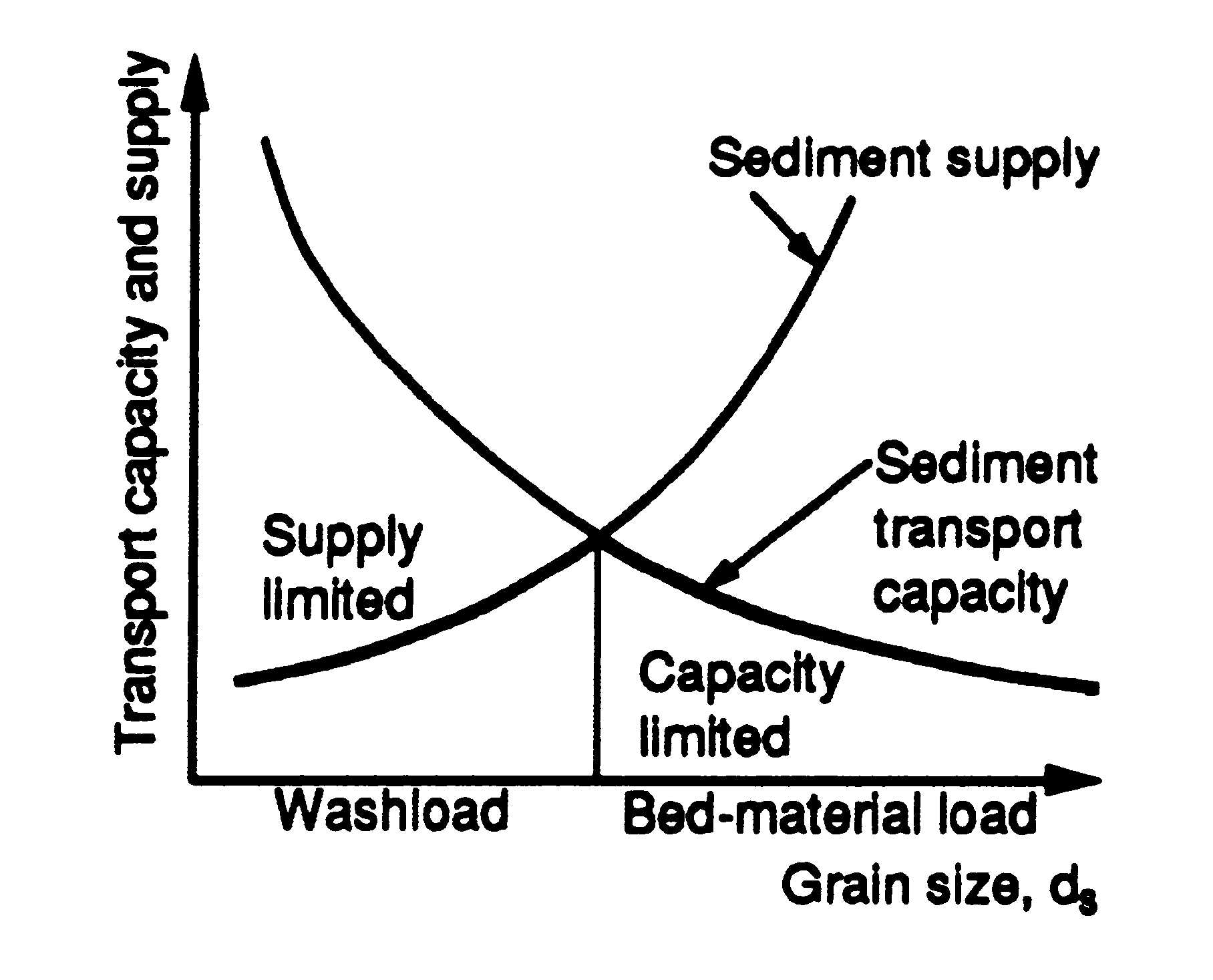
Once a soil particle erodes, it becomes part of the flow and is transported downstream. A particle moving past a control must have eroded somewhere in the watershed upstream of the cross section, and it must be transported by the flow from the point of detachment to the point of interest (Einstein 1950). Each of these two requirements may control the sediment rate at the cross section: the availability of sediment in the watershed and the transport capacity of the stream. Typically, the finer material, which is easily carried in large amounts by the flow, has limited availability in the watershed. The coarse material is much more difficult to move by flows, so its rate of movement is limited by the transport capacity of the flow (Haan et al 1994). Julien (1995) used Figure 5 to explain the concept of supply and transport limited capacity. Figure 5. Sediment transport capacity and supply curves (Julien 1995). It is often assumed that the washload travel through a system by stream flow with very little deposition and is carried primarily in suspension. Coarser fractions tend to move as bed-material. In addition, particles moving in suspension at one place may be moving as bed-material further downstream. The total sediment discharge or total sediment load, consist of both bed-material load and washload. Generally, total sediment load can only be estimated if the washload is estimated by measurements, experiment, or upland sediment yield equation because most sediment transport methods can only determine bed-material load (Haan et al. 1994). Streamwise velocity of sediment particles always lag behind the velocity of the surrounding fluid. This lag is small for the case of silt particles in suspension and large for the case of sands and gravels (Francis 1973). Thus, it is important to predict the movement of the individual sizes found in the flow (Borah et al. 1982). CASC2D-SED uses a 2-D sediment flow routing in the overland that simulates the described transport processes for n numbers of particle sizes. In the overland, CASC2D-SED uses the modified Kilinc & Richardson (1973) transport capacity equation, which depends on flow discharge, terrain slope and soil and land use characteristics. Small particles such as clay and silt move mostly in suspension while the sand fraction moves as bed-material. This is accomplished by using the particle settling concept: coarser particles brought into suspension rapidly settle while small fractions such as clay try to remain in suspension due to its low settling velocity. Once it is in suspension, the suspended size fraction moves by advection. The advective fluxes describe the transport of sediments imparted by velocity currents (Julien 1995). This implies that the sediment will move with the fluid even for capacity limited conditions. The excess transport capacity is defined as the flow capacity to move the bed-material and produce erosion of the parent material once the transported suspended sediment volume is subtracted from the total transport capacity. First, the excess transport capacity is used to move the sediment by size fraction according to its percentage in the bed-material (material deposited earlier in the simulation). For each size fraction, the amount of bed-material that will be transported will be limited by the amount that can be transported by the flow by advection or by the excess transport capacity. Then, if there is any remaining transport capacity once the suspended and bed-material have been transported, the soil is eroded proportionally to the percentage of the corresponding size fraction in the parent material. See Figure 6 and Figure 7 for overland erosion and sediment transport processes schematics and flowchart, respectively. The volumes of deposited or eroded material translate into a change in the corresponding cell elevation at each time step. At the end of the simulation, the input DEM is modified according to the elevation change in each cell.
Sediment by size fraction is routed in the channels using the Engelund and Hansen (1967) transport equation in 1-D for n numbers of particle sizes. This formulation depends on hydraulic parameters (hydraulic radius, flow velocity and friction slope) and particle characteristics (specific gravity and particle diameter). For each of those fractions, a transport capacity is calculated using the Engelund and Hansen equation. For a particular size fraction, the excess transport capacity is calculated by subtracting the amount of sediment carried in suspension by advective processes from the transport capacity. The bed-material is transported using the excess transport capacity. The amount of transported bed-material is calculated as the minimum between the amount that can be carried by advective processes and the excess transport capacity. Channels are not allowed to erode in CASC2D-SED and thus, the remaining transport capacity is not used. See Figure 8 and Figure 9 for overland erosion and sediment transport processes schematics and flowchart, respectively.
The transported material (from suspension, bed-material or parent material) is transferred from the outgoing cell into the suspended portion of the receiving cell. Once the sediment has been routed for all the overland and channel cells in the watershed in the x- and y-direction, the sediment in suspension is allowed to settle. For a given sediment size fraction at a given cell, the volume of suspended sediment that will settle depends on the total volume of that fraction in suspension, on the particle settling velocity and the water depth at the given cell.
Julien & Simons (1984) derived a general relationship supported by dimensional analysis that can be written as a power function of slope and discharge. The unit upland sediment discharge from sheet and rill erosion can be written in the form (Julien & Simons 1984):
where: So = surface slope m/m] q = unit discharge [m2/s] qs = sediment unit discharge a, b, g = coefficients The values of the exponents b and g range typically between 1.2 < b < 1.9 and 1.4 < g < 2.4 (Julien & Simons 1984). In 1972, Kilinc (1972) studied experimentally and analytically the mechanics of soil erosion from overland flow generated by simulated rainfall. The main objectives of his research were to study the most important factors affecting soil erosion, and to develop a soil loss prediction equation. Experiments were conducted at the rainfall-runoff facilities at the Engineering Research Center of the Colorado State University. Data was collected for sediment concentration, surface velocity of overland flow, water discharge, water temperature, infiltration rate, bulk density of surface soil, slope, intensity of rainfall, and rill geometry. Some of the conclusions from derived from the study of Kilinc were: a) the Reynolds number and slope were the most important parameters in sediment transport prediction equations; b) the Reynolds number, rainfall excess, and water discharge each had the same significance and influence on sediment transport from overland flow; and c) sediment discharge increases with the square of water discharge and 5/3 power of the slope. This model was comparable to that used by Meyer and Wischmeier (1969). The Kilinc and Richardson (1973) equation was developed for the estimation of sheet and rill erosion from bare soils. In the more general case of erosion from sheet flow, modifications to the last equation reflect the influence of soil type, vegetation, and practice factor using the USLE factors K, C, and P as (Julien 1995):
where: qs = unit sediment discharge [tons m-1 s-1] So = terrain slope [m m-1] q = unit flow discharge [m2 s-1] K = erodibility factor in the USLE equation [--] C = cropping management factor in the USLE equation [--] P = conservation practice factor in the USLE equation [--] For a grid of cell size, Dx [m], and for a time interval, Dt [s], the total volume "sKR [m3] of sediment coming from a cell is calculated as:
On the other hand, the rate of mass transport carried by advection for size fraction i, qsADVi [m3 s-1] per unit area A [m2], is obtained from the product of size fraction i sediment concentration, Ci [m3 m-3], and the average flow velocity component, V [m s-1] (Julien 1995):
Simplifying and integrating for a time step Dt [s], the volume (in m3) of suspended sediment size fraction, i, that can be transported by advection is:
where SusVoli [m3] is the size fraction i suspended volume. The volume of size fraction i transported from the suspended portion of the source cell, "ssusi, into the receiving cell is found as the maximum value between the amount of sediment that can be carried by advection and the amount calculated using the Kilinc and Richardson equation:
The transport capacity is then reduced by the amount of sediment in suspension that is carried from the source cell. The total excess capacity (totXSScap) of the flow to carry sediments is:
This excess capacity is used to transport the sediment from the bed-material in the source cell. The volume of size fraction i transported from the bed-material, "sBMi, [m3] is found as:
where BMvoli [m3] is the volume of size fraction i found in the source cell bed-material. Once the sediment in suspension and the bed-material are transported and provided that there is still remaining capacity left, the soil is eroded proportionally to the percentage of fraction i in the parent material, Pi:
where "sEROSi [m3]is the volume of size fraction i eroded from the parent material. This algorithm provides a better transition between supply-limited and capacity-limited sediment transport calculations.
The eroded material in the upland portion of the watershed is transported to the outlet through the channels. Erosion is not allowed to occur in the channels. Thus, transport might be supply limited. Deposition of material is allowed. The Engelund and Hansen (1967) equation is used to calculate the sediment transport capacity in the channels.
where: G = sediment specific gravity V = channel depth-averaged velocity [m s-1] Sf = channel friction slope [m m-1] g = gravitational acceleration [m2 s-1] dsi = size fraction i diameter [m] Rh = channel hydraulic radius [m] The volume of size fraction i, "sEHi [m3] that can be transported during a time interval, Dt [s], is estimated as:
where: Q = flow discharge in the channel [m3 s-1] Cwi = sediment concentration by weight of size fraction i The volume of suspended sediment size fraction i, "sSUSi [m3], that is transported in the channels by advection is:
The excess transport capacity for a given fraction i, XSScapi [m3], is used to carry size fraction i channel bed-material.
On the other hand, the volume of fraction i bed-material that can be transported by advection in the channel is proportional to:
where BMvoli [m3] is the volume of size fraction i found in the bed-material. The volume of size i bed-material that will be finally transported from the bed-material, "sBMi, is found to be the minimum between the excess transport capacity and the volume of the bed-material that can be carried by advection for that size fraction:
In the case in which there is still remaining transport capacity, this will not be used, as channels are not currently allowed to erode in CASC2D-SED.
A particle falling in turbulent free water moves in response to the difference in the submerged weight of the particle and the drag of the fluid on the particle. At steady state, the forces in equilibrium are described by:
where: CD = drag coefficient, normally a function of the Reynolds number, Re d = particle diameter rs = particle density r = fluid density ws = particle settling velocity g = acceleration of gravity Stokes showed that the drag for spheres depends on the Reynold's number:
where Re depends on the kinematic viscosity, n:
For the Stokes' range (i.e. Re < 0.5). Equation 3-30 can be simplified to yield (Haan et al. 1994; Julien 1995)
where G is the specific gravity of the particles. The settling velocity of large particles (> 0.2 mm and Re > 0.5), can be estimated with the following relationship (Julien 1995):
Assuming, medium sediment particle diameter for the sand, silt and clay fractions, the following fall velocities are estimated (see Table 1): Table 1. Particle mean diameter and fall velocity.
Once the sediment has been routed in overland and channel cells, the suspended sediment portion is allowed to deposit. CASC2D-SED assumes a discrete particle settling type in which particles tend to fall independently of each other as discrete particles. The percentage of suspended sediment fraction i, PercSetti, that is allowed to settle depends on the fall velocity corresponding to the median size fraction diameter, wi [m/s], elapsed time (i.e. computational time step, Dt [s]) and water depth d [m] in the cell.
The volume of suspended sediment that settles in a given time increment is subtracted from the suspended sediment portion and added to the deposited one. This algorithm improves upon the trap efficiency algorithm by allowing continuous sedimentation of the suspended load in the backwater areas. Home | Registration | Background | Processes | References | Example | Download | Feedback Department of Civil and Environmental Engineering - Colorado
State University |