|
|
|||||
|
|
The CASCade 2 Dimensional SEDiment (CASC2D-SED) model originally began with a two-dimensional overland flow routing algorithm developed and written in APL by Prof. P.Y. Julien at Colorado State University. The overland flow routing module was converted from APL to FORTRAN by Saghafian, then at Colorado State University, with the addition of Green & Ampt infiltration, detention storage and diffusive-wave channel routing (Julien and Saghafian 1991; Saghafian 1992; Julien et al. 1995). CASC2D was incorporated as part of the GRASS GIS for hydrologic simulations as r.hydro.CASC2D (Saghafian 1993; Saghafian and Ogden 1996). Later on, Ogden (1994) added the implicit channel routing option to CASC2D. Since 1995, CASC2D has been reformulated with the addition of continuous simulation capabilities and other hydrological components such as interception, initial depths, evapotranspiration and redistribution (Ogden 1997b). This last version is incorporated in the Watershed Modeling System (WMS) Interface developed by Brigham Young University (2001) and is known as CASC2D for WMS. The upland erosion and channel sediment transport module was added by Johnson (1997) based in previous work done by Kilinc (1972) and Kilinc and Richardson (1973) at Colorado State University and was called CASC2D-SED. The sediment transport algorithms developed by Rojas (2002) improve over the version of Johnson et al. (2000) in the following manner: (1) improves simulation of the transition between supply-limited and capacity-limited sediment transport; (2) allows transport by advection of suspended material even when the transport capacity is negligible; and (3) improves simulation of sedimentation in backwater areas.
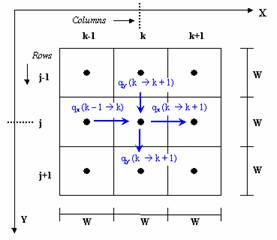
CASC2D solves the equations of conservation of mass, energy and linear momentum to estimate watershed runoff for a given rainfall input. The overland flow routing formulation is based on an explicit 2-dimensional finite difference (FD) technique. An explicit FD technique is used for the routing of 1-dimensional channel flow. To understand the method by which the CASC2D model conducts its calculations, it is important to conceptualize the two dimensional spatial nature and resolution of the given watershed data. The explicit numerical solution is achieved by segmenting the entire catchment area into equal square elements, which are then assigned parameters relating to soil infiltration characteristics, roughness coefficients, and soil erosion parameters (Spah 2000). As each parameter is defined, it is assumed to be uniform throughout the cell area with the actual value assigned to a central nodal point. Figure 1 provides a visual illustration of how the grid concept within the CASC2D model is defined for a small nine-cell section of a watershed (Julien and Saghafian). Figure 1. A Typical Two-Dimensional Model Grid Mesh (Julien and Saghafian 1991). The process by which CASC2D transports runoff through a defined channel network is based on a one-dimensional, diffusive wave approximation scheme. This scheme is mathematically similar to that used for overland flow computations. As the modeled rainfall event progresses, overland flow is routed through the overland planes until the flow reaches a channel location. This flow is then transformed into a channel flow component and routed through the channel network to the defined outlet location. During the flow routing process, channel losses or gains are neglected. The channel network defined in a CASC2D project is made up of links, numbered according to the computational order. A channel link is made up of connected grid cells, called the nodes of that particular link. Each node describes the channel reach represented by that node with geometric and hydraulic characteristics. The channel cross section is assumed to be rectangular. The flow occurs from one cell center to the neighboring cell center in any of the eight flow directions. The channel is assumed to be located in the middle of the grid cell as shown in Figure 2. Figure 2. Channel cross section. CASC2D simulations involving channel flow is able depict time varying backwater effects for simulated runoff flows. These backwater effects are continuous as they are carried through all associated channel junctions within the defined stream network (Saghafian 1992). The computational time step in channels is first equal to the simulation time step. In the case in which the channel routing becomes unstable at a given time step, this time step is cut in half and the flow is routed in the channel network in two smaller steps. If the the channel depth still becomes negative, the time step is divided again by two. This process is repeated until the water can be routed in the channels without being unstable or until the time step becomes unreasonably small (<0.0001). Home | Registration | Background | Processes | References | Example | Download | Feedback Department of Civil and Environmental Engineering - Colorado
State University |