|
|
HYDROLOGICAL AND SEDIMENT PROCESSES |
|
Overview | |
|
|
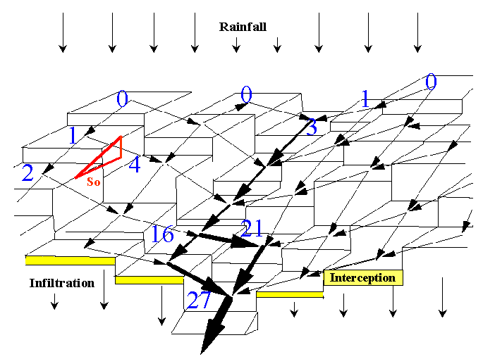
CASC2D has been developed to determine the runoff hydrograph generated from any temporally-spatially varied rainfall event. When using the erosion/sedimentation module of CASC2D, sediment rates can be predicted at any location as well. For a given rainfall event, once the initial losses have been subtracted from rainfall, water begins to infiltrate. This step requires the adoption of an infiltration scheme that can predict the portion of the rainfall that drains into the ground. The Green & Ampt (1911) infiltration equation accommodates spatial and temporal variabilities due to changes in the rainfall and/or soils properties, and takes into account the accumulated infiltration. Using a Hortonian overland flow process, when the precipitation rate exceeds the infiltration rate, the excess rainfall will accumulate as surface water and begin to flow. In CASC2D, overland flow is routed into the channels using a diffusive wave approximation in two dimensions. In channels, the water is routed using a 1-D diffusive wave equation. The erosion/sedimentation rates are calculated as a function of the hydraulic properties of the flow, the physical properties of the soil and the surface characteristics. The modified Kilinc-Richardson equation (Julien, 1995) is used in CASC2D-SED to determine the upland sediment transport by grain size from one cell into the next one in two orthogonal directions. The sediment coming from upland erosion is routed through the channel network into the outlet. Follow the Flow Routing link to see the governing equations in the overland flow and channel routing schemes. The equations used in estimating precipitation, interception, infiltration and base flow are also included in this page. Finally, the processes of upland and channel erosion and deposition are described in the Sediment Routing page. Figure 3 shows the CASC2D-SED routing scheme. Figure 4 shows the CASC2D-SED code routines flow chart. Figure 3. Topographical representation of overland flow and channel routing schemes.
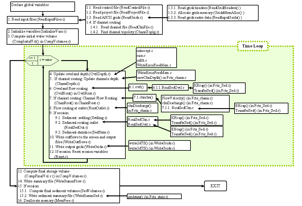
Figure 4. CASC2D-SED routines flow chart (clickto enlarge). Home | Registration | Background | Processes | References | Example | Download | Feedback Department of Civil and Environmental Engineering - Colorado
State University |