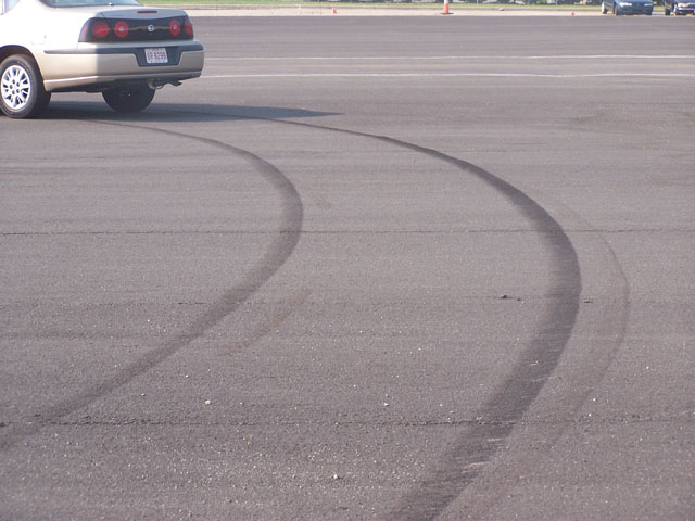
A Critical Speed Yaw is a manuver that a vehicle undergoes as a result of maximum lateral forces applied to the tires. The marks left by the tires after a critical speed yaw are distiqushed by their curvature and diagonal striations. An example of critical speed yaw marks are shown in the photo below.
The marks in the above photo are generated when the rear of the tire contact patch breaks free from the pavement. While the mechanism for makring may not be fully understood, the marks to represent the path of travel for the individual tires. The thickest and darkest scuff mark was generated by the outside front tire. There is a lighter mark on the outside left by the outside rear tire. Under low speed turning conditions, the rear tires will typically track inside the front tires; however, during a CSY, the rear tires will track outside the front tires. There is a point where the rear tire mark and the front tire mark conerge. Sometimes this is referred to as the crosover point. If the outside tire marks do not separate too far from the front tire marks, then the front (dark) mark can represent the path of the vehicle.
The speed of the center of mass of the vehicle can be determined (in mph) with the following formula: S=3.86*sqrt(r*f) where r is the radius and f is the drag factor. The draf factor accounts for the slope of the surface and the friction. It is a measure of the maximum amount of lateral acceleration (in g's) possible for the center of mass of the car.
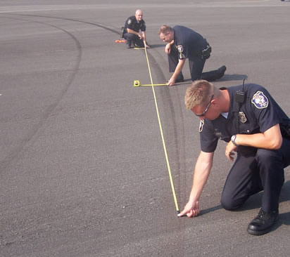
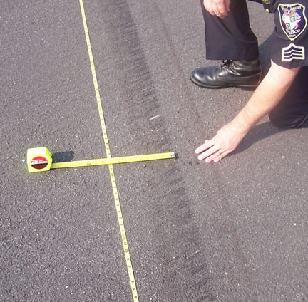
Often the curved marks are assumed to be circular and the radius of the marks can be determined by measuring a chord and middle ordinate. The formula for determining radius from a chord and middle ordinate is r = c^2/(8*m) + m/2, which is sensitive to small middle ordinate measures. Careful measurements are shown in the following photos.
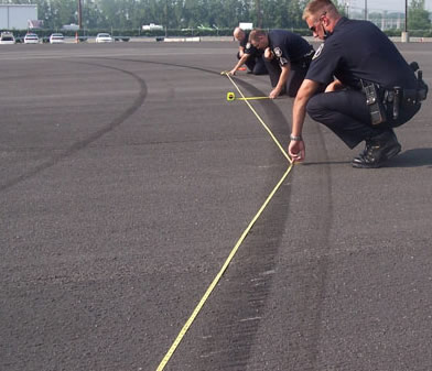
Notice the last photo shows the measureing team measureing the CSY mark starting from the end of the first chord. Another radius determination can be made from these measurements. Interstingly, many CSY marks show a decreasing radius. A spiral curve also has a decreasing radius. Therefore, the subject of this project is to explore the ability to use spirals to determine a contstantly changing radius observed from CSY manuvers.
The goal of this project is to compare speed determinations based on the radii from the well-known chord and middle ordinate technique, the speeds predicted using a spiral geometry, and know speed records from a Racelogic VBox 3i and Radar. The literature shows the chord an middle ordinate method, when properly used can produce reliable speed estimates. It is proposed that a spiral fit may provide both reliable and more detailed estimates of speed because the radius of curvature will be defined as a continuus function.
When a vehicle is performing a critical speed yaw, we will model it as a particle with its mass concentrated at the center of mass. The amount of energy from rotation is much smaller that the kinetic energy in translation, thus making this assumption appropriate. Also, we will assume no out-of-plane motion, so the path of the vehicle is described using two dimensions. Often vertical curves have much less curvature than the yaw mark itself. The vehicle will enter the CSY manuver from an initial speed, v_o. The vehicle will experience a constant lateral acceleration as a result from the steering action of the tires. This is afundamental assumption od the CSY analysis -- the lateral acceleration is not changing significantly.
Since the path of travel is known based on the scuff marks, a tangent-normal coordinate system can represent the kinematics of motion using the following LaTeX formula:
\vec{a}=a*\hat{u_t}+v^2/\rho * \hat{u_n}
which says that the total acceleration vector comprises an unknown acceleration in the tangent direction and an acceleration in the normal direction equal to the velocity squared divided by the radius of curvature. Based on the idea of a friction circle, the maximum amount of force available to change the velocity of the car is the mass times the gravity times the drag factor. Applying Newton's second law, F=ma, results in the vehicle mass cancelling out and the magnitude of the acceleration is f*g.