Prelab
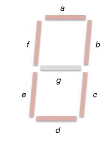
Any decimal digit from zero through nine can be displayed by lighting the appropriate segments of a 7-segment display, as shown below in Figure 1:
THE SEVEN-SEGMENT DISPLAY
Figure 1: Segment definitions of a 7-segment display.
The desired decimal digit is expressed in
binary-coded-decimal (BCD) format, and then used as an input to
a logic network which controls the seven segments.
For this project, you will develop a multiple-output logic
network that drives a 7-segment display, yielding all ten
decimal digits. Here is how you will proceed:
1. The input variables will be the BCD representations of the decimal digits 0-9 (use switches 0-3 on your DE board: SW0= LSB, SW3= MSB).
2. Using Karnaugh maps, determine the seven output functions for controlling each of the seven segments, in minimum SOP (AND-OR) form. Using Don't Cares will greatly simplify your output functions.
3. Also express the seven output functions in OR-AND (POS) form.
4. (Optional) Rewrite output functions in step3 using NOR gates (NOT gates are permissible).
You will display the digit on the left 7-segment digit on your DE board. Refer to the DE Manuals regarding how to enable a specific digit on this display. Hint: Applying a logic low level to a segment causes it to light up and applying a high level turns it off.
Design Constraints: Use 2-, 3-, or 4-input gates, except that inverters may be used to invert input variables. A design with 20 or fewer total gates ( AND and OR) is required.